Thermodynamic cycle
Thermodynamic cycle
Gas Power Cycles
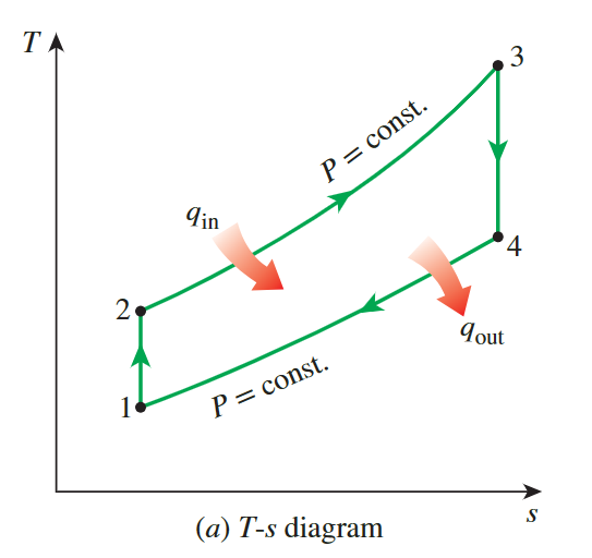
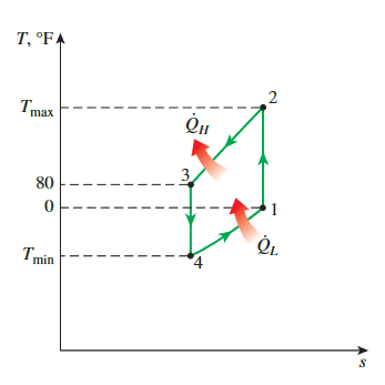
Carnor cycle
**isothermal inversible**
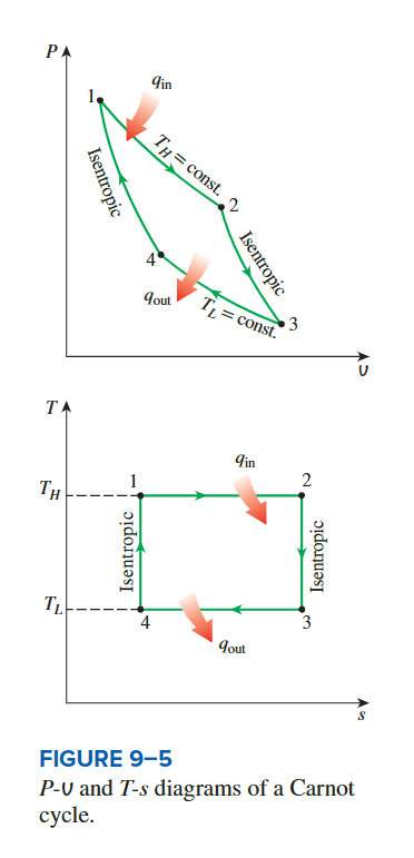
The efficiency of the Carnor cycle
the heat transfer is during the 2 process
**isothermal inversible**
so ,the amount of heat input and heat output for the cycle can be expressed as:
\[ q_{\text {in }}=T_H\left(s_2-s_1\right) \]
\[ q_{\text {out }}=T_L\left(s_3-s_4\right)=T_L\left(s_2-s_1\right) \]
we see that the thermal efficiency of a Carnot cycle is:
\[ \eta = \frac{q_{in}-q_{out}}{q_{in}} = 1-\frac{T_L}{T_H} \]
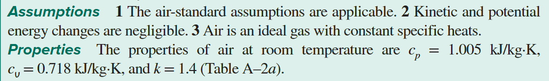
Un Example of an Air-Standard Cycle
the ideal gas isentropic relationandideal gas relation
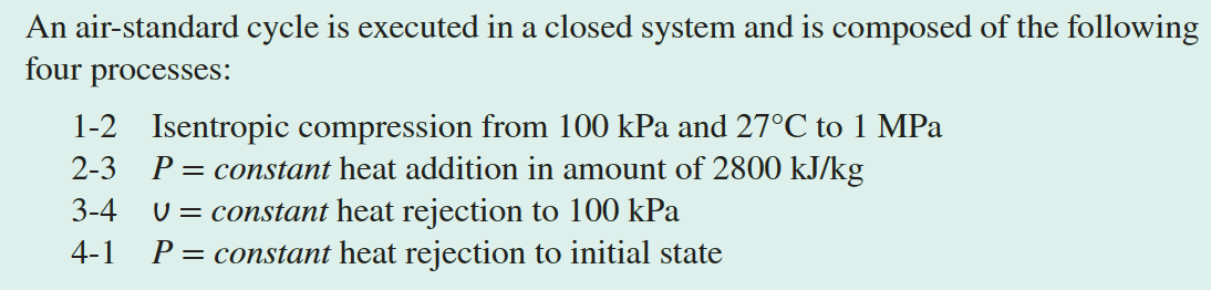
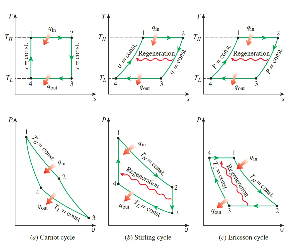
Show the cycle on P-v and T-s Diagrams
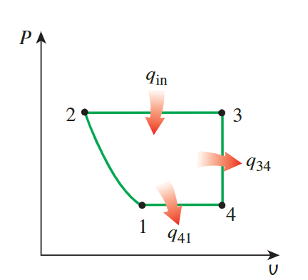
For the P-v diagram, it's observed that
processes 2-3, 3-4, and 4-1 are isobaric
or isochoric, represented by
straight lines. The 1-2 process is an
**isentropic compression**, where volume decreases and
pressure increases, which is shown as a curve extending to the upper
left direction.
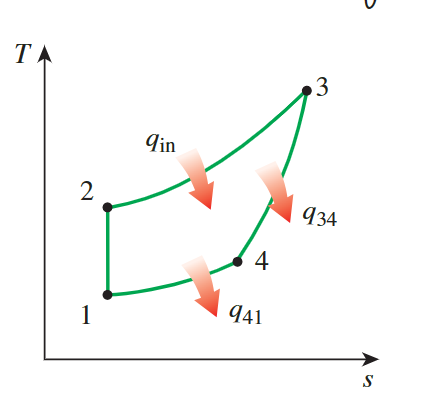
For the T-s diagram, the 1-2 process is isentropic,
reflected as a
**vertical line**. From 2-3, heat is added at constant
pressure, **causing** the temperature and entropy
**to rise**. From 3-4, heat is removed at constant volume,
**leading to a decrease** in temperature and entropy. When
heat is removed at constant pressure, both temperature and entropy
decrease.
calculate the maximum temperature in the cycle
1-2
- \(P_1 = 100kPa, T_1 = 300.15K\)
- \(P_2 = 1000kPa\),
for the ideal gas isentropic relation
\[ T_2=T_1\left(\frac{P_2}{P_1}\right)^{(k-1) / k}=(300 \mathrm{~K})\left(\frac{1000 \mathrm{kPa}}{100 \mathrm{kPa}}\right)^{0.4 / 1.4}=579.2 \mathrm{~K} \]
2-3
- \(q_{in} = 2800kJ/kg = h_{2-3},\)
- \(h_{2-3} = c_p(T_3-T_2)\)
- \(2800 \mathrm{~kJ} / \mathrm{kg}=(1.005 \mathrm{~kJ} / \mathrm{kg} \cdot \mathrm{K})\left(T_3-579.2\right) \longrightarrow T_{\max }=T_3=3360 \mathrm{~K}\)
Determine the thermal efficiency
3-4
- form the
**ideal gas relation**for a fixed mass
\[ \frac{P_3 V_3}{T_3}=\frac{P_4 V_4}{T_4} \longrightarrow T_4=\frac{P_4}{P_3} T_3=\frac{100 \mathrm{kPa}}{1000 \mathrm{kPa}}(3360 \mathrm{~K})=336 \mathrm{~K} \]
the total amount of
**heat rejected**\[ q_{out} = q_{34,out}+q_{41,out} = (u_3-u_4)+(h_4-h_1) \]
Note, the positive value of the heat radiated is taken here.
the thermal efficiency:
\[ \eta_{\text {th }}=1-\frac{q_{\text {out }}}{q_{\text {in }}}=1-\frac{2212 \mathrm{~kJ} / \mathrm{kg}}{2800 \mathrm{~kJ} / \mathrm{kg}}=0.210 \text { or } 21.0 \% \]
The ideal Otto Cycle
looking up Table A-17 &
**linear interpolation** &**power output**
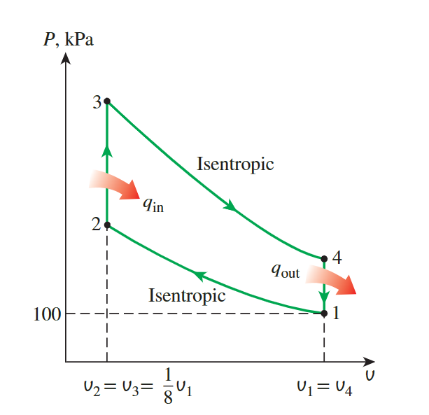
An ideal Otto cycle has a **compression ratio** of 8. At
the beginning of the compression process, air is at 100 kPa and 17°C,
and 800 kJ/kg of heat is transferred to air during the constant-volume
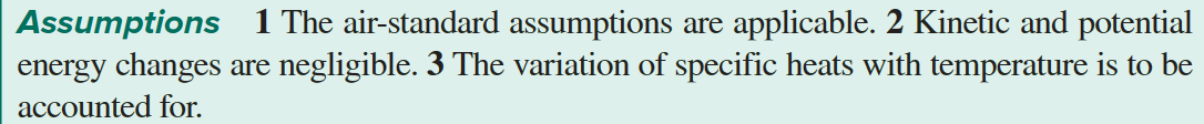
heat-addition process. Accounting for the variation of specific heats of
air with temperature, determine
the maximum temperature and pressure that occur during the cycle
1-2
- \(P_1 = 100kPa,T_1 = 290K\)
- Because the heat capacity changes with temperature need to be considered, data is obtained by looking up Table A-17.
- heat is transferred during the constant volume heat addition process, so we look up u rather than h
\[ \begin{aligned}T_1=290 \mathrm{~K} \rightarrow u_1 & =206.91 \mathrm{~kJ} / \mathrm{kg} \\V_{r 1} & =676.1\end{aligned} \]
by the compression radio: \(V_{r_2} = \frac {V_{r1}} r = 84.51\)
- From the table A-17, By using the method of
**linear interpolation** we get:
\[ \begin{aligned}& T_2=652.4 \mathrm{~K} \\& u_2=475.11 \mathrm{~kJ} / \mathrm{kg}\end{aligned} \]
**After obtaining**the temperature, we can get the pressure using the ideal gas relation.\[ \begin{aligned}\frac{P_2 V_2}{T_2}=\frac{P_1 V_1}{T_1} \rightarrow P_2 & =P_1\left(\frac{T_2}{T_1}\right)\left(\frac{V_1}{V_2}\right) \\& =(100 \mathrm{kPa})\left(\frac{652.4 \mathrm{~K}}{290 \mathrm{~K}}\right)(8)=1799.7 \mathrm{kPa}\end{aligned} \]
- From the table A-17, By using the method of
2-3
- \(q_{in} = 800kJ/kg = c_v(T_3-T_2)\)
- but the variation of specific can not be neglect, so we check the table A-17
- \(u_3 = u_2+q_{in} = 1275.11kJ/kg\)
- \(T_3 = 1575.1K, V_{r 3}=6.108\) by the linear interpolation
\[ \begin{aligned}\frac{P_3 V_3}{T_3}=\frac{P_2 V_2}{T_2} \rightarrow P_3 & =P_2\left(\frac{T_3}{T_2}\right)\left(\frac{V_2}{V_3}\right) \\& =(1.7997 \mathrm{MPa})\left(\frac{1575.1 \mathrm{~K}}{652.4 \mathrm{~K}}\right)(1)=4.345 \mathrm{MPa}\end{aligned} \]
the net work output
we need to find the internal energy of
the air at 4
3-4
\[ \begin{aligned}\frac{V_{r 4}}{V_{r 3}}=\frac{V_4}{V_3}=r \rightarrow V_{r 4}=r V_{r 3}=(8)(6.108)=48.864 \rightarrow & T_4=795.6 \mathrm{~K} \\& u_4=588.74 \mathrm{~kJ} / \mathrm{kg}\end{aligned} \]
4-1
\[ \begin{aligned} -q_{\text {out }} & =u_1-u_4 \rightarrow q_{\text {out }}=u_4-u_1 \\ q_{\text {out }} & =588.74-206.91=381.83 \mathrm{~kJ} / \mathrm{kg} \end{aligned} \]
由此得到净功:
\[ w_{\text {net }}=q_{\text {net }}=q_{\text {in }}-q_{\text {out }}=800-381.83=\mathbf{4 1 8 . 1 7 ~} \mathbf{~ J J} / \mathbf{k g} \]
the thermal efficiency
\[ \eta_{\text {th }}=\frac{w_{\text {net }}}{q_{\text {in }}}=\frac{418.17 \mathrm{~kJ} / \mathrm{kg}}{800 \mathrm{~kJ} / \mathrm{kg}}=0.523 \text { or } 52.3 \% \]
under the cold-aire-standard assumption:
\[ \eta_{\text {th,Otto }}=1-\frac{1}{r^{k-1}}=1-r^{1-k}=1-(8)^{1-1.4}=0.565 \text { or } 56.5 \% \]
the
mean effective pressure for the cycle.
- the mean effective pressure:
\[ \mathrm{MEP}=\frac{w_{\text {net }}}{v_1-v_2}=\frac{w_{\text {net }}}{v_1-v_1 / r}=\frac{w_{\text {net }}}{v_1(1-1 / r)} \]
where
\[ \mathrm{v}_1=\frac{R T_1}{P_1}=\frac{\left(0.287 \mathrm{kPa} \cdot \mathrm{m}^3 / \mathrm{kg} \cdot \mathrm{K}\right)(290 \mathrm{~K})}{100 \mathrm{kPa}}=0.8323 \mathrm{~m}^3 / \mathrm{kg} \]
**power output**
Also, determine the power output from the cycle, in kW, for an engine speed of 4000 rpm (rev/min). Assume that this cycle is operated on an engine that has four cylinders with a total displacement volume of 1.6 L
the total aire mass taken by all four cylinders:
\[ m=\frac{V_d}{U_1}=\frac{0.0016 \mathrm{~m}^3}{0.8323 \mathrm{~m}^3 / \mathrm{kg}}=0.001922 \mathrm{~kg} \]
the net work:
\[ W_{net}=m w_{\text {net }}=(0.001922 \mathrm{~kg})(418.17 \mathrm{~kJ} / \mathrm{kg})=0.8037 \mathrm{~kJ} \]
there are two revolutions per thermodynamic cycle
\[ \dot{W}_{\text {net }}=\frac{W_{\text {net }} \dot{n}}{n_{\text {rev }}}=\frac{(0.8037 \mathrm{~kJ} / \text { cycle })(4000 \mathrm{rev} / \mathrm{min})}{2 \mathrm{rev} / \text { cycle }}\left(\frac{1 \mathrm{~min}}{60 \mathrm{~s}}\right)=26.8 \mathrm{~kW} \]
The Ideal Diesel Cycle
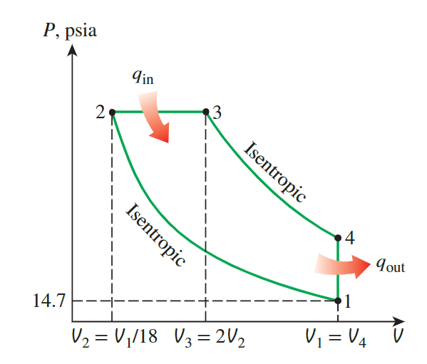
the temperature and pressure of air at the end of each process
because the constant specific heats, we can use the ideal gaz isentropic relation and ideal gaz relation:
\[ \begin{aligned}& T_2=T_1\left(\frac{V_1}{V_2}\right)^{k-1}=(540 \mathrm{R})(18)^{1.4-1}=\mathbf{1 7 1 6} \mathbf{R} \\& P_2=P_1\left(\frac{V_1}{V_2}\right)^k=(14.7 \mathrm{psia})(18)^{1.4}=\mathbf{8 4 1} \text { psia }\end{aligned} \]
\[ \begin{gathered}P_3=P_2=841 \text { psia } \\\frac{P_2 V_2}{T_2}=\frac{P_3 V_3}{T_3} \rightarrow T_3=T_2\left(\frac{V_3}{V_2}\right)=(1716 \mathrm{R})(2)=3432 \mathbf{R}\end{gathered} \]
\[ \begin{aligned}& T_4=T_3\left(\frac{V_3}{V_4}\right)^{k-1}=(3432 \mathrm{R})\left(\frac{13 \mathrm{in}^3}{117 \mathrm{in}^3}\right)^{1.4-1}=\mathbf{1 4 2 5} \mathbf{~ R} \\& P_4=P_3\left(\frac{V_3}{V_4}\right)^k=(841 \mathrm{psia})\left(\frac{13 \mathrm{in}^3}{117 \mathrm{in}^3}\right)^{1.4}=\mathbf{3 8 . 8} \mathbf{~ p s i a}\end{aligned} \]
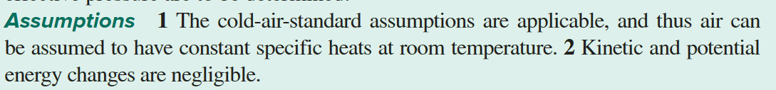
Stirling and Ericsson Cycle
**entropy change of an ideal gas**
thermal efficiency
- we know that
\[ \begin{gathered}d s=\frac{C_v}{T} d T+\left(\frac{\partial P}{\partial T}\right)_V \cdot d V \\d s=\frac{C_P}{T} d T-\left(\frac{\partial V}{\partial T}\right)_P \cdot d p\end{gathered} \]
- so the entropy change of an ideal gas during an isothermal process:
\[ \Delta s = c_pln\frac{T_e}{T_i}-Rln\frac{P_e}{P_i} = c_vln\frac{T_e}{T_i}+Rln\frac{V_e}{V_i}\\=Rln\frac{P_e}{P_i}=Rln\frac{V_e}{V_i} \]
- thermal efficiency
\[ \eta = 1-\frac {q_{in}}{q_{out}} = 1-\frac{T_L\Delta s_{3,4}}{T_L\Delta s_{2,1}} \]
- for ecrisson cycle, we have\(P_1 = P_4,P_2 = P_3\) so we can get \(\Delta s_{3,4} = \Delta s_{1,2}\)
- for Stirling cycle, we have \(V1 = V_4, V_2 = V_3\) so we can get\(\Delta s_{3,4} = \Delta s_{1,2}\)
- at all, we can calcul the thermal efficiency
\[ \eta = 1-\frac {q_{in}}{q_{out}} = 1-\frac{T_L}{T_L} \]
with the same result as the Carnot cycle
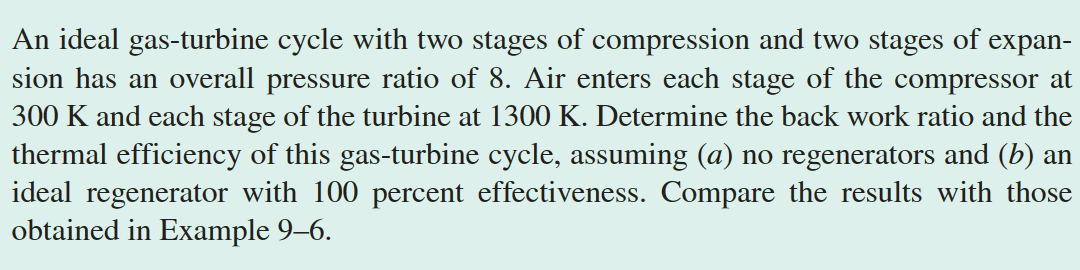
Brayton Cycle
**the back work radio**
the gas temperature at the exits of the compressor and the turbine
- the variation of specific heats with temperature is to be considered, so we need to look up the data in the table A-17
- Because heat addition and removal are isobaric processes, we use enthalpy instead pf internal
- we can easily know the pressure of \(P_1,P_2,P_3,P_4\),and we know \(T_1\) so we can get \(P_{r1}\)
- with the relation:
\[ P_{ri} = \frac{P_i}{P_1}P_{r1} \]
- we can get all the data we need
**the back work radio**
- we firstly find the work input to the
compressorand the work output of theturbine
\[ \begin{gathered} w_{\text {comp,in }}=h_2-h_1=544.35-300.19=244.16 \mathrm{~kJ} / \mathrm{kg} \\ w_{\text {turb,out }}=h_3-h_4=1395.97-789.37=606.60 \mathrm{~kJ} / \mathrm{kg} \end{gathered} \]
- Thus, the back work radio is defined as:
\[ r_{\text {bw }}=\frac{w_{\text {comp,in }}}{w_{\text {turb,out }}}=\frac{244.16 \mathrm{~kJ} / \mathrm{kg}}{606.60 \mathrm{~kJ} / \mathrm{kg}}=\mathbf{0 . 4 0 3} \]
- That is , 40.3 percent of the turbine work output is used just to drive the compressror
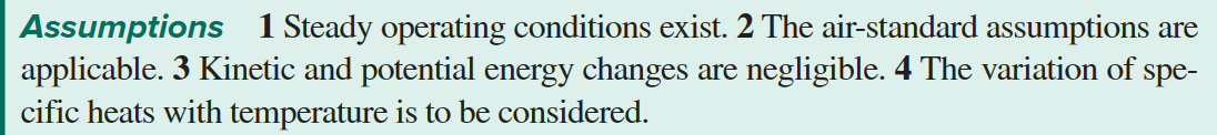
Actual Gas-Turbine Cycle
**compressor efficiency**and**turbine efficiency**
from actual work to actual temperature
back work ratio
For actual problems, we calculate the work using the standard model and deal with efficiency
\[ \begin{gathered}w_{\text {comp,in,actual }}=\frac{w_{comp,in}}{\eta_C}=\frac{244.16 \mathrm{~kJ} / \mathrm{kg}}{0.80}=305.20 \mathrm{~kJ} / \mathrm{kg} \\w_{turb,out,actual }=\eta_T w_{turb,out }=(0.85)(606.60 \mathrm{~kJ} / \mathrm{kg})=515.61 \mathrm{~kJ} / \mathrm{kg}\end{gathered} \]
- we dont need to memorize the calculation ordre, as long as we know that the actual input is greater than the theoretical input and the actual output is less than the theoretical output
- Thus:
\[ r_{\text {bw }}=\frac{w_{\text {comp,in }}}{w_{\text {turb,out }}}=\frac{305.20 \mathrm{~kJ} / \mathrm{kg}}{515.61 \mathrm{~kJ} / \mathrm{kg}}=\mathbf{0 . 5 9 2} \]
The air temperature at the turbine exit
- The enthalpy of an isentropic process 3 and actual work can be used to calculate the enthalpy exit of a turbine, which can then be looked up in a table to obtain the temperature
\[ \begin{aligned}w_{\text {turb,out ,actual}}=h_3-h_{4 a} \rightarrow h_{4 a} & =h_3-w_{\text {turb,out ,actual}} \\& =1395.97-515.61 \\& =880.36 \mathrm{~kJ} / \mathrm{kg}\end{aligned} \]
- Then, from Table A–17,
\[ Then, from Table A–17, \]
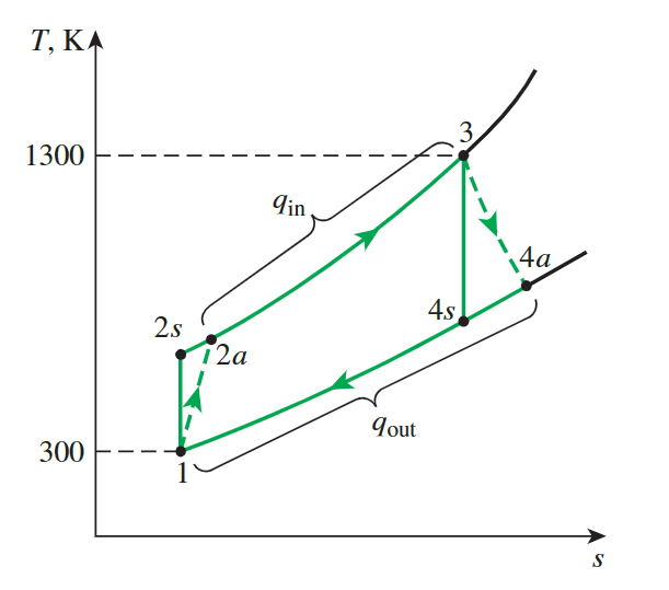
Actual Gas-Turbine Cycle with Regeneration
**effectiveness of regenerator**
effectiveness of regeneration
It is important to understand the meaning of regeneration and calculate the effectiveness of regeneration
\[ \epsilon=\frac{h_5-h_{2 a}}{h_{4 a}-h_{2 a}} \]
\[ q_{\mathrm{in}}=h_3-h_5=(1395.97-825.37) \mathrm{kJ} / \mathrm{kg}=570.60 \mathrm{~kJ} / \mathrm{kg} \]
Regeneration improves efficiency by reducing the input heat.
Throughout this process, the net power remains unchanged.
\[ w_{turb,out,actual} = h_{4a}-h_3 \]
This give the efficiency
\[ \eta_{th} = \frac{w_{turb,out,acutual}}{q_{in}} \]
A Gas Turbine with Reheating and Intercooling
**same pressure ratio**&**same temperature and enthalpy**
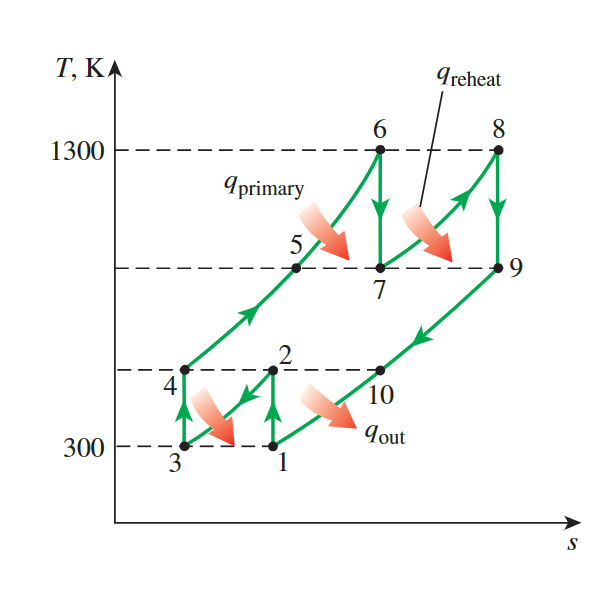

same pressure ratio & same temperature and enthalpy
the work output is maximized when both stages of he compressor and the turbine have the same pressure ratio-the overall pressure radio
\[ \frac{P_2}{P_1}=\frac{P_4}{P_3}=\sqrt{8}=2.83 \text { and } \frac{P_6}{P_7}=\frac{P_8}{P_9}=\sqrt{8}=2.83 \]
the temperature and enthalpy of the air at the exit of each compression stage will be the same:
At inlets: \(\quad T_1=T_3, h_1=h_3\) and \(T_6=T_8, \quad h_6=h_8\) At exits: \(\quad T_2=T_4, h_2=h_4\) and \(T_7=T_9, h_7=h_9\)
same work input & output
as the result, the work input to each stage of the compressor and the work output from each stage of the turbine will be same:
\[ \begin{gathered}w_{\text {comp,in }}=2\left(w_{\text {comp,in, } \mathrm{I}}\right)=2\left(h_2-h_1\right)=2(404.31-300.19)=208.24 \mathrm{~kJ} / \mathrm{kg} \\w_{\text {turb,out }}=2\left(w_{\text {turb,out, } \mathrm{I}}\right)=2\left(h_6-h_7\right)=2(1395.97-1053.33)=685.28 \mathrm{~kJ} / \mathrm{kg} \\w_{\text {net }}=w_{\text {turb,out }}-w_{\text {comp,in }}=685.28-208.24=477.04 \mathrm{~kJ} / \mathrm{kg}\end{gathered} \]
Simultaneously, the added heat.
\[ \begin{aligned}q_{\text {in }} & =q_{\text {primary }}+q_{\text {reheat }}=\left(h_6-h_4\right)+\left(h_8-h_7\right) \\& =(1395.97-404.31)+(1395.97-1053.33)=1334.30 \mathrm{~kJ} / \mathrm{kg}\end{aligned} \]
Thus:
\[ r_{\text {bw }}=\frac{w_{\text {comp,in }}}{w_{\text {turb,out }}}=\frac{208.24 \mathrm{~kJ} / \mathrm{kg}}{685.28 \mathrm{~kJ} / \mathrm{kg}}=\mathbf{0 . 3 0 4} \]
and
\[ \eta_{\mathrm{th}}=\frac{w_{\text {net }}}{q_{\text {in }}}=\frac{477.04 \mathrm{~kJ} / \mathrm{kg}}{1334.30 \mathrm{~kJ} / \mathrm{kg}}=0.358 \text { or } \mathbf{3 5 . 8 \%} \]
an ideal regenerator with 100 percent effectiveness.
the net work don’ t change
The heat input and the thermal efficiency in this case are
\[ \begin{aligned}q_{\text {in }} & =q_{\text {primary }}+q_{\text {reheat }}=\left(h_6-h_5\right)+\left(h_8-h_7\right) \\& =(1395.97-1053.33)+(1395.97-1053.33)=685.28 \mathrm{~kJ} / \mathrm{kg}\end{aligned} \]
\[ \eta_{\text {th }}=\frac{w_{\text {net }}}{q_{\text {in }}}=\frac{477.04 \mathrm{~kJ} / \mathrm{kg}}{685.28 \mathrm{~kJ} / \mathrm{kg}}=0.696 \text { or } \mathbf{6 9 . 6 \%} \]
The Ideal Jet-Propulsion Cycle
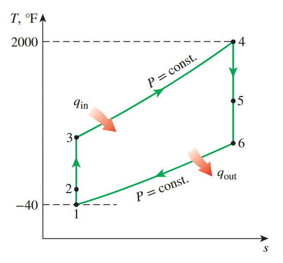
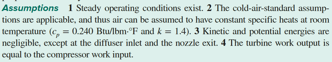
State 2: air exit the diffuser with a negligible velocity
Process 1-2 isentropic compression of an ideal gas in a diffuser
\[ h_2+\frac{V_2^2}{2}=h_1+\frac{V_1^2}{2}\Leftrightarrow T2 = T1+\frac{V_1^2}{2c_p} \]
- \(T_2 = 480R\)
- we can look up the pressure of state 2, but as the unite is not standard, we use the isentropic relations:
\[ P_2 = P_1\cdot(\frac{T_1}{T_2})^{k/(k-1)} \]
State 3: The pressure ratio
Process 2-3 isentropic compression of an ideal gaz
\[ P_3=\left(r_p\right)\left(P_2\right) \]
State 5 : the turbine work to be equal to the compressor work
\[ \begin{aligned}w_{\text {comp,in }} & =w_{\text {turb,out }} \\h_3-h_2 & =h_4-h_5 \\c_p\left(T_3-T_2\right) & =c_p\left(T_4-T_5\right) \\T_5 & =T_4-T_3+T_2=2460-927+480=\mathbf{2 0 1 3} \mathbf{R}\end{aligned} \]
State 6: the aire velocity at the nozzle exit
\[ \begin{aligned}h_6+\frac{V_6^2}{2} & =h_5+\frac{V_5^2}{2} \\0 & =c_p\left(T_6-T_5\right)+\frac{V_6^2}{2}\end{aligned} \]
Efficiency
\[ \dot{W}_P=\dot{m}\left(V_{\text {exit }}-V_{\text {inlet }}\right) V_{\text {aircraft }}\\\eta_P=\frac{\dot{W}_P}{\dot{Q}_{\text {in }}} \]
Vapor and Combined Power Cycles
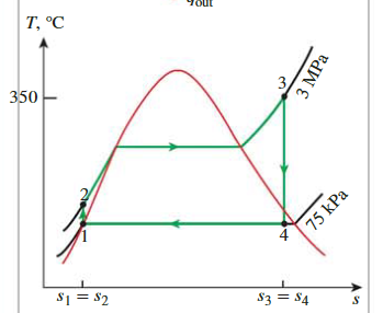
The Simple Ideal Rankine Cycle

Four Stage
State 1-2
\[ \begin{aligned}& \left.P_1=75 \mathrm{kPa}\right\} \quad h_1=h_{f @ 75 \mathrm{kPa}}=384.44 \mathrm{~kJ} / \mathrm{kg} \\& \text { Sat. liquid }\} v_1=v_{f @ 75 \mathrm{kPa}}=0.001037 \mathrm{~m}^3 / \mathrm{kg} &\end{aligned} \]
State 2-3
\[ \begin{aligned}w_{\text {pump,in }} & =v_1\left(P_2-P_1\right)=\left(0.001037 \mathrm{~m}^3 / \mathrm{kg}\right)[(3000-75) \mathrm{kPa}]\left(\frac{1 \mathrm{~kJ}}{1 \mathrm{kPa} \cdot \mathrm{m}^3}\right) \\& =3.03 \mathrm{~kJ} / \mathrm{kg} \\h_2 & =h_1+w_{\text {pump,in }}=(384.44+3.03) \mathrm{kJ} / \mathrm{kg}=387.47 \mathrm{~kJ} / \mathrm{kg}\end{aligned} \]
State 3-4
\[ \begin{aligned}& s_4=s_3 \\& x_4=\frac{s_4-s_f}{s_{f g}}=\frac{6.7450-1.2132}{6.2426}=0.8861 \\& h_4=h_f+x_4 h_{f g}=384.44+0.8861(2278.0)=2403.0 \mathrm{~kJ} / \mathrm{kg}\end{aligned} \]
Efficiency
\[ \begin{aligned}&\begin{gathered}q_{\text {in }}=h_3-h_2=(3116.1-387.47) \mathrm{kJ} / \mathrm{kg}=2728.6 \mathrm{~kJ} / \mathrm{kg} \\q_{\text {out }}=h_4-h_1=(2403.0-384.44) \mathrm{kJ} / \mathrm{kg}=2018.6 \mathrm{~kJ} / \mathrm{kg}\end{gathered}\\&\eta_{\text {th }}=1-\frac{q_{\text {out }}}{q_{\text {in }}}=1-\frac{2018.6 \mathrm{~kJ} / \mathrm{kg}}{2728.6 \mathrm{~kJ} / \mathrm{kg}}=0.260 \text { or } 26.0 \%\end{aligned} \]
An Actual Steam Power Cycle
isentropic efficiency
\[ w_{\text {pump,in }}=\frac{w_{s, \text { pump,in }}}{\eta_P}=\frac{v_1\left(P_2-P_1\right)}{\eta_P};\quad w_{\text {turb,out }}=\eta_T w_{s, \text { turb,out }}; \]
\[ w_{\text {net }}=w_{\text {turb,out }}-w_{\text {pump,in }} \]
The Ideal Reheat Rankine Cycle
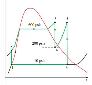

Cycle
- State 1:
- \(\begin{aligned}& h_1=h_{f @ 10 \mathrm{psia}}& U_1=U_{f @ 10 \mathrm{psia}}\end{aligned}\)
- State 2:
- \(w_{\text {pump,in }}=U_1\left(P_2-P_1\right)\)
- \(h_2=h_1+w_{\text {pump,in }}\)
- State 3:
- \(\left.\begin{array}{l}P_3=600 \mathrm{psia} \\T_3=600^{\circ} \mathrm{F}\end{array}\right\} \begin{aligned}& h_3=1289.9 \mathrm{Btu} / \mathrm{lbm} \\& s_3=1.5325 \mathrm{Btu} / \mathrm{lbm} \cdot \mathrm{R}\end{aligned}\)
- State 4:
- \(x_4=\frac{s_4-s_f}{s_{f g}}=\frac{1.5325-0.54379}{1.00219}=0.9865\)
- \(h_4=h_f+x_4 h_{f g}\)
- State 5:
- \(\left.\begin{array}{l}P_5=200 \mathrm{psia} \\T_5=600^{\circ} \mathrm{F}\end{array}\right\} \begin{aligned}& h_5=1322.3 \mathrm{Btu} / \mathrm{lbm} \\& s_5=1.6771 \mathrm{Btu} / \mathrm{lbm} \cdot \mathrm{R}\end{aligned}\)
- State 6:
- \(x_6=\frac{s_6-s_f}{s_{f g}}=\frac{1.6771-0.28362}{1.50391}=0.9266\)
- \(h_6=h_f+x_6 h_{f g}\)
Efficiency
\[ \begin{gathered}q_{\text {in }}=\left(h_3-h_2\right)+\left(h_5-h_4\right) \\q_{\text {out }}=h_6-h_1\\w_{\text {net }}=q_{\text {in }}-q_{\text {out }}\end{gathered} \]
Ideal Regenerative Rankine Cycle
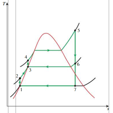

Cycle
- state 1:
- \(P_1 = 10kPa\) , State 1 is the saturated liquid, we can look up the table
- \(h_1 = 191.81kJ/kg\), \(v_1 = 0.001010m^3/kg\)
- state 2:
- \(h_2 = h_1+v_1(P_2-P_1) = 193.01kJ/kg\)
- state 3:
- \(P_2 = P_3 = 1.2MPa\), State 3 is the saturated liquid, we can look up the table
- \(h_3 = 798.33kJ/kg, v_3 = 0.001138M^3/kg\)
- state 4:
- \(h_4 = h_3+v_3(P_4-P_3) = 814.0344kJ/kg\)
- state 5:
- \(P_5 = 15MPa, T_5 = 600\degree C\), state 5 is the process overheated,
- \(h_5 = 3539.0kJ/kg, v_5 = 0.018185m^3/kg\)
- \(s_5 = 6.6796 kJ/kg.K\)
- \(h_5=3583.1 \mathrm{~kJ} / \mathrm{kg}\)
- state 6
- from state 5 to state 6, the process is isentropic
- \(s_6 = s_5 = 6.6796 kJ/kg.K\)
- we have \(P_6 = 1.2MPa\), by looking up table \(T_6 = 218.45\degree C\)
- \(h_6=2860.2 \mathrm{~kJ} / \mathrm{kg}\)
- state 7
- from state 6 to state 7, the process is isentropic
- \(s_7 = s_5 = 6.6796 kJ/kg.K\)
- The pressure of state 7: \(P_7 = 10kPa\)
- we can look up the table: \(s_f = 0.6492, s_{fg} = 7.4996\)
- Thus, the quality \(x = \frac{s_7-s_f}{s_{fg}} = 0.8041\)
- We can get the enthalpy: \(h_7 = 191.81+0.8041\cdot 2392.1 = 2115.29\)
The fraction of steam extracted from the turbine
\[ y = \frac{\dot m_6}{\dot m_5}=\frac{h_3-h_2}{h_6-h_2} = 0.2270 \]
Efficency
\[ \begin{aligned}&\begin{aligned}q_{\text {in }} & =h_5-h_4=(3583.1-814.03) \mathrm{kJ} / \mathrm{kg}=2769.1 \mathrm{~kJ} / \mathrm{kg} \\q_{\text {out }} & =(1-y)\left(h_7-h_1\right)=(1-0.2270)(2115.3-191.81) \mathrm{kJ} / \mathrm{kg} \\& =1486.9 \mathrm{~kJ} / \mathrm{kg}\end{aligned}\\&\eta_{\text {th }}=1-\frac{q_{\text {out }}}{q_{\text {in }}}=1-\frac{1486.9 \mathrm{~kJ} / \mathrm{kg}}{2769.1 \mathrm{~kJ} / \mathrm{kg}}=0.463 \text { or } 46.3 \%\end{aligned} \]
Refrigration Cycles
The Ideal Vapor-Compression Refrigeration Cycle
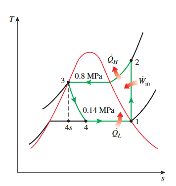

throttling
\[ \begin{aligned}& P_1=0.14 \mathrm{MPa} \longrightarrow h_1=h_{g @ 0.14 \mathrm{MPa}}=239.19 \mathrm{~kJ} / \mathrm{kg} \\& s_1=s_g @ 0.14 \mathrm{MPa}=0.94467 \mathrm{~kJ} / \mathrm{kg} \cdot \mathrm{K} \\& \left.\begin{array}{l}P_2=0.8 \mathrm{MPa} \\s_2=s_1\end{array}\right\} h_2=275.40 \mathrm{~kJ} / \mathrm{kg} \\& P_3=0.8 \mathrm{MPa} \longrightarrow h_3=h_{f @ 0.8 \mathrm{MPa}}=95.48 \mathrm{~kJ} / \mathrm{kg} \\& h_4 \cong h_3(\text { throttling }) \longrightarrow h_4=95.48 \mathrm{~kJ} / \mathrm{kg} \\&\end{aligned} \]
COP
\[ \begin{aligned}&\dot{Q}_L=\dot{m}\left(h_1-h_4\right)=(0.05 \mathrm{~kg} / \mathrm{s})[(239.19-95.48) \mathrm{kJ} / \mathrm{kg}]=7.19 \mathrm{~kW}\\&\dot{W}_{\text {in }}=\dot{m}\left(h_2-h_1\right)=(0.05 \mathrm{~kg} / \mathrm{s})[(275.40-239.19) \mathrm{kJ} / \mathrm{kg}]=\mathbf{1 . 8 1} \mathbf{k W}\end{aligned} \]
\[ \mathrm{COP}_{\mathrm{R}}=\frac{\dot{Q}_L}{\dot{W}_{\text {in }}}=\frac{7.19 \mathrm{~kW}}{1.81 \mathrm{~kW}}=\mathbf{3 . 9 7} \]
A Two-Stage Cascade Refrigeration Cycle
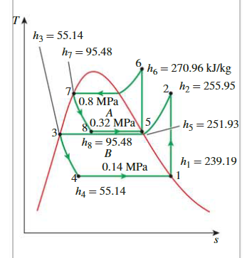
steady-flow energy balance
\[ \begin{aligned}\dot{E}_{\text {out }}=\dot{E}_{\text {in }} \longrightarrow \dot{m}_A h_5+\dot{m}_B h_3 & =\dot{m}_A h_8+\dot{m}_B h_2 \\\dot{m}_A\left(h_5-h_8\right) & =\dot{m}_B\left(h_2-h_3\right) \\(0.05 \mathrm{~kg} / \mathrm{s})[(251.93-95.48) \mathrm{kJ} / \mathrm{kg}] & =\dot{m}_B[(255.95-55.14) \mathrm{kJ} / \mathrm{kg}] \\\dot{m}_B & =\mathbf{0 . 0 3 9 0} \mathrm{kg} / \mathrm{s}\end{aligned} \]
COP
\[ \begin{aligned}\dot{Q}_L=\dot{m}_B( & \left.h_1-h_4\right)=(0.0390 \mathrm{~kg} / \mathrm{s})[(239.19-55.14) \mathrm{kJ} / \mathrm{kg}]=7.18 \mathrm{~kW} \\\dot{W}_{\text {in }}= & \dot{W}_{\text {comp I,in }}+\dot{W}_{\text {comp II,in }}=\dot{m}_A\left(h_6-h_5\right)+\dot{m}_B\left(h_2-h_1\right) \\= & (0.05 \mathrm{~kg} / \mathrm{s})[(270.96-251.93) \mathrm{kJ} / \mathrm{kg}] \\& +(0.039 \mathrm{~kg} / \mathrm{s})[(255.95-239.19) \mathrm{kJ} / \mathrm{kg}] \\= & \mathbf{1 . 6 1} \mathbf{k W}\end{aligned} \]
\[ \mathrm{COP}_{\mathrm{R}}=\frac{\dot{Q}_L}{\dot{W}_{\text {net,in }}}=\frac{7.18 \mathrm{~kW}}{1.61 \mathrm{~kW}}=4.46 \]
A Two-Stage Refrigeration Cycle with a Flash Chamber
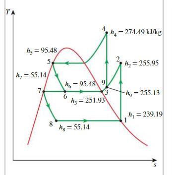
Quality of state 6
\[ x_6=\frac{h_6-h_f}{h_{f g}}=\frac{95.48-55.14}{196.78}=\mathbf{0 . 2 0 5 0} \]
Enthalpy at state 9
\[ h_9=x_6 h_3+\left(1-x_6\right) h_2 \]
Work in
\[ w_{\text {in }}=w_{\text {comp I,in }}+w_{\text {comp II,in }}=\left(1-x_6\right)\left(h_2-h_1\right)+(1)\left(h_4-h_9\right) \]
\(Q_L\)
\[ \begin{aligned}q_L & =\left(1-x_6\right)\left(h_1-h_8\right) \\& =(1-0.2050)[(239.19-55.14) \mathrm{kJ} / \mathrm{kg}]=\mathbf{1 4 6 . 3} \mathbf{k J} / \mathbf{k g}\end{aligned} \]
COP
\[ \mathrm{COP}_{\mathrm{R}}=\frac{q_L}{w_{\text {in }}}=\frac{146.3 \mathrm{~kJ} / \mathrm{kg}}{32.68 \mathrm{~kJ} / \mathrm{kg}}=4.48 \]
The Simple Ideal Gas Refrigeration Cycle

- with the assumption of ideal gaz, we can calculate all proprieties with one propriety.
- \(T_1=460 \mathrm{R} \longrightarrow h_1=109.90 \mathrm{Btu} / \mathrm{lbm} \text { and } P_{r 1}=0.7913\)
- \(P_{r 2}=\frac{P_2}{P_1} P_{r 1}=(4)(0.7913)=3.165 \longrightarrow \begin{aligned}& h_2=163.5 \mathrm{Btu} / \mathrm{lbm} \\& T_2=683 \mathrm{R}\left(\text { or } 223^{\circ} \mathrm{F}\right)\end{aligned}\)
- \(T_3=540 \mathrm{R} \longrightarrow h_3=129.06 \mathrm{Btu} / \mathrm{lbm} \text { and } P_{r 3}=1.3860\)
- \(P_{r 4}=\frac{P_4}{P_3} P_{r 3}=(0.25)(1.386)=0.3456 \longrightarrow \begin{aligned}& h_4=86.7 \mathrm{Btu} / \mathrm{lbm} \\& T_4=363 \mathrm{R}\left(\text { or }-97^{\circ} \mathrm{F}\right)\end{aligned}\)
\[ \begin{gathered}\mathrm{COP}_{\mathrm{R}}=\frac{q_L}{w_{\text {net,in }}}=\frac{q_L}{w_{\text {comp,in }}-w_{\text {turb,out }}} \\q_L=h_1-h_4=109.9-86.7=23.2 \mathrm{Btu} / \mathrm{lbm} \\w_{\text {turb,out }}=h_3-h_4=129.06-86.7=42.36 \mathrm{Btu} / \mathrm{lbm} \\w_{\text {comp,in }}=h_2-h_1=163.5-109.9=53.6 \mathrm{Btu} / \mathrm{lbm}\end{gathered} \]